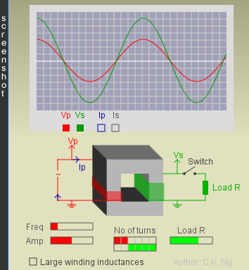
Define
Np = Number of turns in the primary coil
Ns = Number of turns in the secondary coil
Φ p = Magnetic flux in the primary coil
Φ p = Magnetic flux in the secondary coil
Suppose the following conditions are satisfied:
Remarks
Secondary coil is on open circuit
- The primary coil behaves as a pure inductor.
- The only current flowing is the primary current (Ip).
- The flux linking the two coils is caused by Ip. This primary current is called magnetizing current (Ip,M).
- The primary voltage (Vp) leads the magnetizing current (Ip,M) by π/2.
- Average input power = 0
Resistive load R is connected to the secondary coil
- The secondary current (Is) becomes nonzero.
- Is is always in phase with Vs, because the load is a pure resistor.
- The flux linking the two coils is still caused by Ip,M.
- Besides the manetizing current, the primary current has one more component (call it Ip,L), which is anti-phase with the secondary current Is, i.e.,
Ip = Ip,M + Ip,L, where Ip,M and Ip,L are π/2 out of phase.
By Lenz’s law, Is must flow in a direction such that the change of magnetic flux in the core is reduced.
However, the change of flux in the core always produces a voltage in the primary coil to have the same value as the a.c. source voltage (since the input loop is resistanceless).
To maintain this, the primary current eventually becomes larger to restore the original magnetic flux, compensating the opposition due to the secondary current.
Eventually, the core flux is still produced by Ip,M,while the fluxes produced by Ip,L and Is cancel each other out.
- The primary voltage (Vp) leads the primary current (Ip) by an angle θ = tan-1( R/Xs), where Xs is the reactance of the secondary coil.
- Average input power = Vp,rmsIp,rmscos(θ)
If the load R is decreased,
- Ip,L will be further increased, but Ip,M remains the same, and
- the phase angle between the primary voltage and the primary current will be further reduced, approaching zero.
When the load R << Xs (reactance of the secondary coil),
- Ip,L >> Ip,M, hence Ip ≈ Ip,L, and
- the primary voltage is (nearly) in-phase with the primary current.
Any time, VpIp,L = VsIs
Now,VpIp = VsIs
Therefore, Ip : Is = Vs : Vp = Ns : Np
It is noteworthy that
- the voltage ratio Vs : Vp = Ns : Np holds under the two assumptions (i) coils are resistanceless, and (ii) no flux leakage. No matter the secondary coil is open or not, the resistance of R is large or small, the voltage ratio holds, and
- the current ratio Ip : Is = Ns : Np holds when, besides the transformer satisfying the above two assumptions, the resistance of the load R must be sufficiently small (R << Xs).
|